
Preview sample formats for CoC, CTQ inspection reports, and packaging checklists.
ISO 9001 QMS • Inspection evidence • Export-ready delivery
CNC Machining Capabilities in Vietnam
Capability is more than a machine list. SEMIX covers DFM, routing, machining, inspection, finishing coordination, kitting, packaging, and export handoff—built for U.S. and European receiving workflows.
Precision machining
5-axis capable
Inspection reports
Export-ready packaging

Proof
Evidence you can request at RFQ
Capabilities matter when the handoff is receiving‑ready: documented CTQs, packaging discipline, and a clear evidence bundle.
Capability stack
From DFM to delivery
Many suppliers only describe machines. International buyers need more: a workflow that consistently turns drawings into approved parts, supported by evidence. SEMIX organizes capability as an end-to-end system:
DFM review, datum strategy, cost & lead-time optimization, and controlled revision intake.
3-axis, 4-axis, and 5-axis machining for complex geometry and fewer setups.
Turning for shafts and rotational features with strong repeatability and surface quality.
Measurement methods aligned to CTQs: CMM/VMM/hand tools, calibration control, reporting.
CoC, material certs, inspection reports, first-article packages, finishing certificates (as required).
Finishing coordination, re-verification if needed, labeling, kitting, packaging, export shipment support.
What we machine
Typical part categories
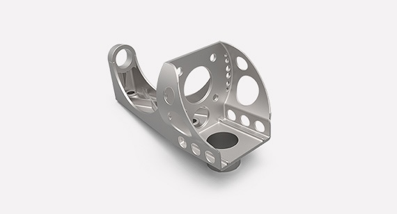
- Precision plates & brackets for equipment assemblies and automation.
- Housings & covers requiring stable datums and clean edge conditions.
- Fixtures, jigs & tooling to support alignment, test, assembly, and calibration.
- Shafts, sleeves & turned parts requiring concentricity and repeatable surface finish.
- Near-net parts (castings/forgings) machined into finished interfaces.
Because “machined parts” is a broad category, we quote based on drawings and requirements. Use the RFQ checklist to avoid missing details that cause quote delays.
Capability planning
How SEMIX controls risk on complex parts
For global supply chains, preventing late-stage issues is critical. SEMIX uses a structured planning approach:
We confirm revision level, critical-to-quality features, inspection method, required documents, packaging requirements, and schedule assumptions before releasing production.
Stable datums reduce variation. For complex multi-face parts, we plan fixtures that protect alignment and reduce setup count.
Verified CAM programs reduce collision risk and improve consistency—especially for 4/5-axis work.
Scheduled checks prevent drift and protect yield. Critical features are checked during machining, not only at final inspection.
Capability snapshot
Capability you can plan around (typical ranges)
A capability page should reduce ambiguity—not inflate claims. The ranges below are typical planning baselines for precision CNC machining programs. Final capability depends on geometry, material behavior, clampings, tool access, and how the characteristic is verified. During RFQ we confirm what is critical (CTQs) and lock the manufacturing + inspection plan to meet it.
| Requirement | Typical planning baseline | What drives it | How it is verified |
|---|---|---|---|
| General dimensional tolerance | Often planned in the ±0.01–0.05 mm range (tighter by review) | Part stiffness, tool reach, clamping strategy, thermal state | Calibrated tools / CMM when appropriate |
| Tight fits (bearing/shaft, slip/press) | Controlled with dedicated finishing strategy and measurement method | Material springback, tool wear, surface integrity | In‑process verification + final measurement under defined conditions |
| GD&T (true position, flatness, perpendicularity) | Planned as a function of clampings and datum simulation (avoid “stacked error”) | Number of setups, datum selection, kinematic chain (especially 5‑axis) | CMM strategy aligned to drawing datums |
| Threads (metric/UN) | Standard thread forms supported; high-load threads reviewed for class and gaging | Material, thread depth, tool access, burr control | Go/No‑Go gages where applicable; measurement notes on request |
| Surface finish | Finish targets set by functional interface; finishing strategy defined in route | Tool condition, chip thickness regime, vibration stability, finishing method | Surface finish check when required + process notes |
| Part size / complexity | Prototype through production; complex multi‑face parts supported with 4‑axis/5‑axis | Machine envelope, fixturing, tool reach, inspection access | Setup verification + inspection plan matched to access constraints |
What “engineering‑credible” capability means
- Capability is tied to a plan: datums, clampings, and inspection method are defined—not assumed.
- CTQs are protected: we identify which features drive function and design the route around them.
- Repeatability beats heroics: we prefer stable methods and verified gates over “one good first article.”
- Evidence is available: inspection reports and documentation packages are designed for receiving and approvals.
Design notes
Design choices that improve capability, yield, and cost
The fastest way to get “engineering‑credible” results is to design the part so it can be made and measured reliably. Below are practical design choices that reduce variation and make global sourcing smoother—without compromising function.
Geometry & tolerancing
- Avoid over‑constraining GD&T: position/flatness should reflect functional need, not aesthetic preference.
- Use datums that can be simulated: if a datum is defined on a fragile surface or a tiny feature, measurement becomes unstable.
- Prefer inspectable requirements: if a feature is critical, ensure there is physical access for probing/gaging.
- Specify edge intent: a controlled edge break prevents burr disputes and improves handling safety.
Machining strategy
- Minimize setups: fewer clampings reduce stack‑up error and improve relational accuracy.
- Leave support where needed: thin walls and long spans benefit from temporary ribs or late‑stage release.
- Plan finish boundaries early: coatings and surface treatments can change inspection conditions and acceptance criteria.
- Call out CTQs: make it clear which features drive function so the process plan targets the right risks.
When you need tighter-than-typical performance
If your drawing includes extremely tight tolerances, unusual GD&T, or thin-wall stability requirements, capability should be confirmed with an explicit plan:
- Agree on measurement conditions (datums, temperature, method) so pass/fail is unambiguous.
- Define a routing strategy (rough → relax → finish gates) if distortion risk exists.
- Confirm inspection evidence (layout/CMM report level) required for receiving.
Materials & process window
Materials, machinability, and what changes the control plan
“Can you machine this material?” is the wrong question. The better question is: what controls are needed to machine it reliably without drift, burr issues, surface damage, or unpredictable tool wear. Different materials push different failure modes, and the process plan should change accordingly.
| Material family | Typical risks | Controls that keep results stable |
|---|---|---|
| Aluminum alloys | Built-up edge (BUE), burrs on thin edges, cosmetic variability | Sharp tools, chip evacuation discipline, edge-break definition, finishing strategy that avoids rubbing |
| Stainless steels | Work hardening, heat generation, burr formation, tool wear drift | Stable chip thickness, controlled feeds, tool-life gating on finishing, deburr planning |
| Titanium / heat‑resistant alloys | Low thermal conductivity → heat at the tool, rapid wear, surface integrity risk | Conservative engagement, coolant strategy, toolpath discipline, verification gates for CTQs |
| Tool steels / hard materials | High cutting forces, tool breakage risk, form/size drift | Rigidity-first fixturing, optimized tool selection, staging (rough → stabilize → finish) |
| Engineering plastics | Thermal expansion, creep, burr/edge behavior, surface marking | Sharp tooling, low heat strategy, handling and fixturing that avoids deformation, defined measurement timing |
Critical interfaces: how capability is “earned”
When a part includes a critical interface (bearing fit, sealing face, precision dowel pattern), the manufacturing plan must protect it. A credible capability claim includes the controls below—matched to your CTQs.
- Finish strategy for the interface (dedicated finishing tools, controlled tool wear window).
- In‑process verification on a sentinel feature that predicts final outcome.
- Defined edge condition on functional surfaces (no ambiguous “deburr”).
- Inspection method agreement for pass/fail clarity at receiving.
Related insights
Build Vietnam sourcing confidence
These guides are written to support international procurement and engineering teams evaluating a CNC machining supplier in Vietnam.
What to ask, how to qualify a supplier, and how to avoid common sourcing risks.
When to choose 5-axis, what it changes, and what data improves quoting accuracy.
Tolerances, inspection planning, and documentation packages that matter for approvals.