
Executive takeaway
Residual stress is not a “metallurgy topic.” In precision CNC machining it behaves like a hidden state variable that determines whether geometry is stable after unclamping, after finishing, after plating/anodize, and sometimes even after shipping.
World‑class suppliers treat residual stress as an engineering risk that is:
- observable (via distortion studies and targeted residual-stress measurements),
- predictable (via stock‑removal symmetry + stiffness/compliance reasoning), and
- controllable (via routing gates: rough → relax → semi → relax → finish).
This brief provides an applied framework for aerospace and semiconductor‑adjacent hardware where flatness, thin‑wall stability, and fatigue/cleanliness risks are high. It also explains when and how to use ASTM E837 hole‑drilling to validate your strategy and to produce buyer‑grade evidence.
1) Residual stress: the engineering definition that matters in production
Residual stress is the self‑equilibrated stress field that remains in a part after external loads are removed. It is not “one number”; it is a spatial field σ(x,y,z) whose consequences depend on:
- distribution through thickness (stress gradient and where the neutral axis sits),
- part compliance (thin webs, long spans, asymmetric ribs),
- constraint history (how the part is clamped and when it is released), and
- subsequent processing (heat, finishing, coating, shot peen, weld, EDM).
1.1 Macro vs micro residual stress (why measurement method selection matters)
Practically, residual stress appears at different length scales:
- Type I (macro): varies over part‑scale volumes; this is what drives distortion and global warpage.
- Type II (micro): varies between grains/phases (e.g., α/β in Ti alloys); influences crack initiation and some surface reliability behaviors.
- Type III (sub‑micro): within grains; usually relevant to surface treatments and microstructural hardening.
ASTM E837 primarily targets near‑surface in‑plane residual stresses (macro/near‑surface fields), which is exactly what you need for distortion‑and‑stability control, provided the assumptions are respected.
2) Where residual stress comes from in CNC supply chains
A reliable distortion plan starts with a truthful statement: most residual stress you fight was already in the material before the first tool touches it. Machining then redistributes and adds a near‑surface layer on top.
2.1 Pre‑machining sources (material “stress memory”)
- Rolling / plate product: surface/core stress states from non‑uniform deformation and cooling; thin‑wall machining from plate is a common distortion trigger.
- Forging: heterogeneous plastic strain + thermal gradients create spatial stress patterns; local machining removal can unbalance the field.
- Casting: solidification gradients and constraint during cooling can lock stress; machining can “open” the field.
- Heat treatment: quench severity and section thickness produce stress gradients; subsequent machining may release them.
A key production insight: incoming material residual stress is a lot‑to‑lot variable. If your supplier qualification ignores it, your “capability” will look random.
2.2 Machining as a stress‑redistribution process
Machining affects residual stress by three mechanisms:
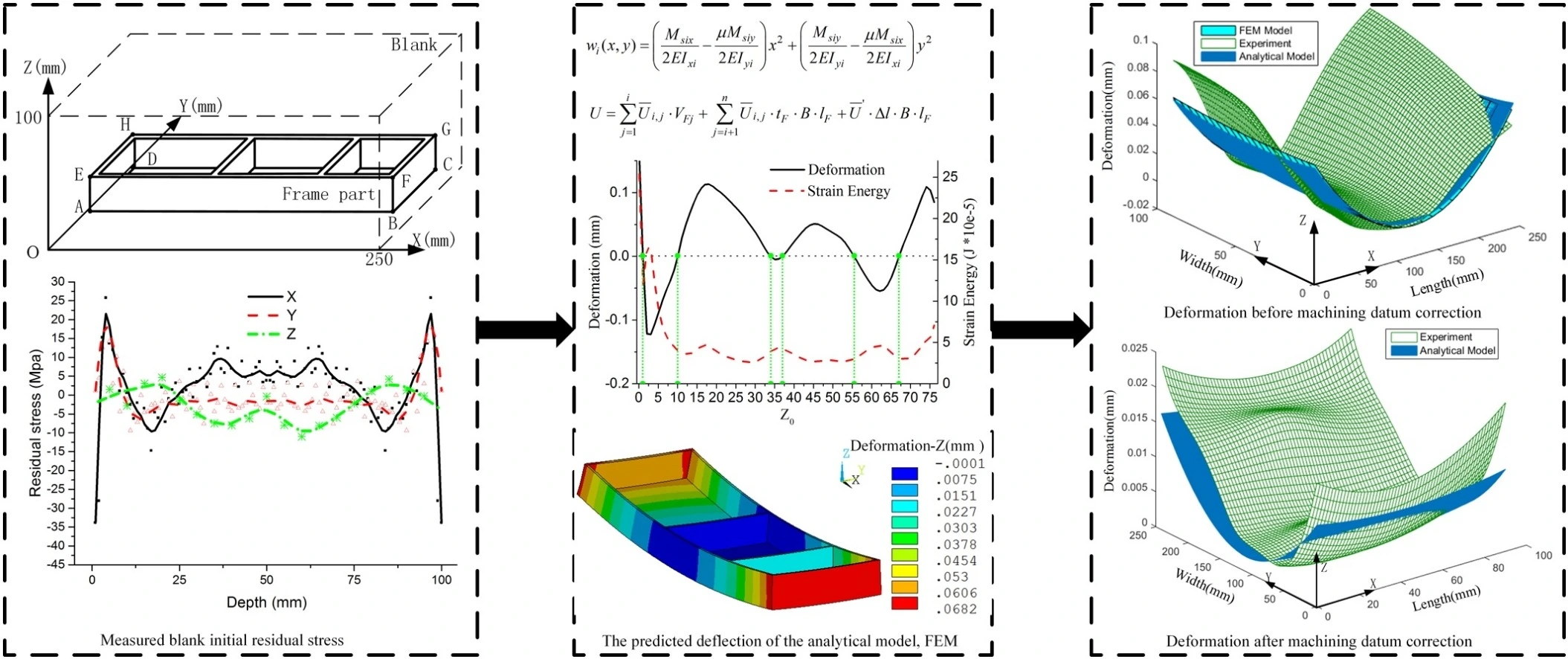
- Equilibrium breaking: removing material removes part of a self‑equilibrated stress field, leaving a net force/moment that the remaining body must balance by deforming.
- Thermo‑mechanical surface loading: cutting heat and near‑surface plasticity create a new stress layer (often the top 10–200 µm depending on process/material).
- Constraint imprinting: over‑clamping can elastically (or plastically) bend thin parts; when you unclamp, the part recovers and geometry shifts.
3) The physics of distortion: why parts move after unclamping
Most “mystery warpage” is simply mechanics. The part moves because stress equilibrium must be restored after you change the body (material removal) or its boundary conditions (unclamp).
3.1 The equilibrium conditions (the core idea)
For a free body (no external loads), the resultant force and moment must be zero. When you machine away material from a stressed plate, the remaining stress field may no longer have zero resultant moment. The part will bend until elastic bending stresses re‑establish equilibrium.
3.2 A practical distortion estimator (thin plate / beam approximation)
For a plate/beam per unit width with thickness t, define z from the mid‑plane. If the remaining residual stress field produces a bending moment per unit width:
M0 = ∫ σ(z) · z dz
then the free‑state curvature is approximately:
κ ≈ − M0 / (E · I), where I = t³/12 per unit width.
This is not a “simulation.” It is a first‑principles reason why thin parts warp: curvature scales with moment / (E·t³). When thickness drops, distortion rises dramatically.
3.3 Worked example (why removing one skin can create millimeter‑level warp)
Consider a Ti alloy plate used for an aerospace bracket. Start thickness 10 mm with a symmetric “skin‑core” stress state (common in wrought product):
- Top and bottom skins: 1 mm each at −200 MPa (compressive)
- Core: 8 mm at +50 MPa (tensile) chosen for force balance
Because the distribution is symmetric, initial bending moment is ~0. Now machine off the top 1 mm skin (asymmetric removal). Remaining thickness t = 9 mm with bottom skin still compressive and core tensile. The resulting net residual moment about the new mid‑plane is on the order of ~1000 MPa·mm² per unit width (order‑of‑magnitude).
Using E ≈ 110,000 MPa (Ti) and I = 9³/12 = 60.75 mm³:
κ ≈ 1000 / (110000×60.75) ≈ 1.5×10⁻⁴ 1/mm
For a 200 mm span, the mid‑span deflection is roughly w ≈ κL²/8 ≈ 0.75 mm. This magnitude is exactly what shops observe: “it was flat in the fixture, then it sprang.”
Production lesson: if you remove stressed skins asymmetrically on thin work, you are “machining curvature into the part.”
3.4 Distortion risk indicators you can compute before cutting
- Asymmetry ratio: unbalanced stock removal (%) between opposite faces.
- Compliance index: span/thickness³ (thin and long is worst).
- CTQ after release: will your tightest CTQs be measured free‑state? If yes, you must design for free‑state stability.
- Thermal sensitivity: if the CTQ is temperature sensitive, you may confuse thermal drift with stress‑release distortion.
4) Machining‑induced residual stress: thermal vs mechanical dominance
Even if incoming material stress were perfect, machining still creates a near‑surface stress layer. The sign and magnitude depend on which driver dominates:
- Mechanical driver (contact pressure / ploughing / burnishing) tends to produce compressive surface stress.
- Thermal driver (high cutting heat + rapid surface cooling) tends to produce tensile surface stress.
Reviews of residual stress across manufacturing highlight that residual stress strongly affects final shape and performance and is often under‑accounted in process planning.
4.1 Why tensile near‑surface stress is a problem for aerospace and semicon‑adjacent parts
- Fatigue / crack initiation: tensile surface stress reduces effective fatigue strength; compressive is generally beneficial.
- Stress‑corrosion susceptibility: tensile stress can accelerate SCC in susceptible alloys/environments.
- Flatness stability: tensile skin + core stress can change how parts relax after finishing or coating.
4.2 Process knobs that shift the stress sign (practical map)
- Tool sharpness & edge radius: worn edges increase ploughing and heat; can drive tensile stress.
- Chip thickness regime: if you cut below minimum chip thickness, friction dominates and heat rises (tensile risk).
- Coolant and thermal management: poor coolant delivery increases thermal gradients.
- Cutting speed vs feed: higher speed without adequate chip evacuation can raise temperature; but material-dependent.
- Finishing passes: extremely light “sparkle” passes can be counterproductive if they enter rubbing/ploughing regime.
5) Measurement methods: choosing the right tool (and what each one can really tell you)
Residual stress is measurable, but each method sees a different “slice” of the truth. A mature supplier selects the method based on the failure mode:
5.1 Quick decision matrix
- X‑ray diffraction (XRD): very near surface; great for surface treatments and machining‑induced stress, but limited penetration.
- ASTM E837 hole‑drilling: near-surface depth profile (semi-destructive), practical for production validation.
- Contour method: destructive but can map 2D residual stress over a section; powerful for root‑cause on thick parts and weldments.
In buyer disputes about distortion, hole‑drilling plus distortion studies is often the best cost‑to‑insight ratio.
6) ASTM E837 hole‑drilling: production‑grade implementation
ASTM E837 standardizes a hole‑drilling strain‑gage method for determining in‑plane residual stresses near the surface of isotropic linear‑elastic materials. The method is applicable where stress gradients across the hole diameter are small, and it can evaluate either “uniform” or “non‑uniform” (depth‑varying) profiles.
6.1 Applicability limits (do not skip these)
- Material behavior: analysis assumes isotropic, linear elastic response; if stress approaches yield, plasticity corrupts results. ASTM listings commonly note applicability when stresses do not exceed about half of yield.
- Geometry: near free edges, results can be biased; ASTM E837‑20 specifies minimum distance to free edge (often expressed relative to gauge circle diameter).
- Thickness: standard “thick body” assumptions may not hold for thin sections; thin‑specimen corrections and validation work exist and should be considered when thickness is comparable to the hole size.
6.2 Why incremental drilling (depth steps) is preferred
Incremental drilling improves versatility and enables depth profiles and gradients to be measured, but only if the experimental practices are meticulous. The NPL Measurement Good Practice Guide highlights that errors and uncertainty can be large when hole geometry and preparation are poor, and that excellent quantitative data is achievable with disciplined practice.
6.3 Step‑by‑step execution checklist (shop‑ready)
- Define the question: Are you validating incoming material, diagnosing distortion, or qualifying a new routing? Pick locations accordingly.
- Select measurement locations: choose CTQ‑relevant zones (thin webs, sealing faces, long spans) and avoid free edges per the standard guidance.
- Prepare the surface: flat, clean, and smooth enough for reliable strain‑gage bonding; surface roughness and flatness matter.
- Install the rosette: correct orientation and concentricity; misalignment is a primary error source.
- Use a proper drilling fixture: alignment and depth control are not optional—hole eccentricity and depth errors dominate uncertainty.
- Drill in controlled increments: record strains at each depth step; allow thermal stabilization between steps if needed.
- Data reduction: use the appropriate method (uniform vs non‑uniform / incremental) and correct material properties (E, ν).
- Report with uncertainty: for buyer-grade reporting, include uncertainty estimates and decision rules (pass/fail with guard bands where required).
6.4 Error sources and how professionals mitigate them
The NPL guide lists practical limitations and common error contributors: hole alignment, diameter, concentricity, profile, depth accuracy, plus surface roughness/flatness and preparation quality. In production terms, this means:
- Use high‑speed, low‑force drilling to minimize additional plastic deformation.
- Control temperature drift (strain gages are sensitive to thermal changes).
- Standardize the setup: same rosette type, same fixture, same drill, same depth increments for repeatability studies.
- Perform a repeatability study on representative coupons to prove the method is stable in your hands.
6.5 Uncertainty: the difference between “data” and “evidence”
If you want U.S./EU buyer trust, you must treat residual stress measurement like metrology. The UNCERT CoP 15 provides a structured procedure to estimate uncertainty for hole‑drilling measurements performed to ASTM E837, including identifying parameters, uncertainty sources, and reporting expanded uncertainty. For broader measurement uncertainty principles aligned with the GUM approach, NIST Technical Note 1297 is a widely cited reference.
7) Distortion gates: turning physics into a repeatable routing
Residual stress control is not a single operation; it is a routing architecture. The goal is to release stress early when there is still material to re‑reference and correct.
7.1 The 3‑gate architecture (rough → relax → semi → relax → finish)
- Gate A (Post‑rough release): remove major stock with symmetry where possible; then release the part from the fixture and measure free‑state distortion. If distortion is large, do not proceed to finish—adjust routing.
- Gate B (Post‑semi release): after semi‑finish, release again to confirm distortion slope is decreasing; this is where you decide if a stress‑relief step is justified.
- Gate C (Pre‑finish stability check): only run final CTQ finishing when the part is stable under the measurement conditions agreed with the buyer.
7.2 Practical machining strategies that reduce stress-driven warpage
- Balanced stock removal: alternate faces; avoid “all from one side” on thin plates.
- Leave support ribs during roughing; remove them late.
- Minimize clamp imprint: use consistent clamp force and avoid bending the part into the fixture.
- Thermal discipline: maintain stable warm-up and restart rules so thermal drift does not mask stress release.
- Finishing strategy: avoid rubbing/ploughing regimes in final passes; keep the tool sharp and chip formation stable.
7.3 Two real-world case patterns (what buyers actually experience)
- Aerospace thin-wall bracket: part passes in-fixture probing but fails free-state flatness. Root cause is asymmetric removal of stressed plate skins + over-clamping during finish. Fix: symmetric roughing + Gate A release + lower clamp force + semi-finish release before final.
- Semiconductor vacuum sealing ring: flatness and leak performance drift after surface finishing/coating. Root cause is near-surface tensile stress layer interacting with process heat + a thin sealing land. Fix: reduce thermal load in finishing, validate with E837 profile on coupons, and specify stabilization/measurement timing in the inspection plan.
8) Buyer-grade evidence package (what convinces U.S./EU quality teams)
- Distortion study report: in‑fixture vs free‑state, by routing gate, with pictures and measured trends.
- Residual stress validation: E837 results on representative material lots / coupons, reported with uncertainty and method control.
- Updated PFMEA + control plan: include stress-related failure modes and reaction plans (containment, re‑verification, routing adjustment).
- Change control: documented actions for material source change, heat treat change, tool strategy change, or fixture redesign.
9) FAQ (buyer intent, long-tail)
- Why does a part pass inspection in the fixture but fail after unclamping?
Because clamping can force the part flat while residual stress remains. Once released, the part deforms to restore equilibrium. - Do you measure residual stress on every order?
Usually no. E837 is used for validation, new-material qualification, or distortion root-cause. Routine control is done via routing gates and distortion trend monitoring. - Can ASTM E837 be used on titanium and aluminum aerospace parts?
Yes if assumptions are respected (linear elastic behavior, geometry limits, edge distance, and stress magnitude relative to yield). - What is the difference between machining-induced stress and material stress?
Material stress is inherited from production history; machining redistributes it and adds a near-surface layer driven by thermal/mechanical loading. - How do you prevent stress-related distortion in high-mix CNC machining?
Use symmetric stock removal, release gates, and standard reaction plans; validate with measurement only where risk justifies it.
Conclusion
Residual stress is manageable when you stop treating distortion as random. Combine three things: (1) symmetry and compliance reasoning, (2) stress-release routing gates, and (3) targeted measurement (ASTM E837) with uncertainty discipline when evidence is required. This is how CNC machining suppliers in Vietnam can reliably support aerospace and semiconductor supply chains without “mystery warpage” surprises.